How to Read Plan and Profile Drawings Storm Drains
How to Read Blueprints: Consummate Guide
Jul 15, 2020

Construction blueprints are technical drawings created by architects, engineers, and designers to put all the construction specifics of a house in one package to which the builder tin refer as they construct the business firm. Although a package of blueprints can be daunting, as many as l pages long, the concept of the blueprint is simple: Information technology is a serial of two-dimensional representations of a three-dimensional edifice.
Professional builder and craftsman Jordan Smith explains in his course on reading blueprints :
"A blueprint is the fundamental programme for the construction of whatsoever construction. The print is what shows the builders, the electricians, the framers – all of the trades people exactly what needs done on whatsoever construction project."
The main sections of a blueprint are:
- Title Sheets and Site Plans
- Flooring Plans
- Elevations and Sections
- Details and Schedules
- Structural Drawings
- Mechanical, Electrical, and Plumbing (MEP) Drawings
Each of these sections uses symbols, scale, and abbreviation to simplify reading the many elements that each plan contains. When you are able to read a design all the way through, you will become a comprehensive understanding of its dimensions, building materials, installation methods, and the mechanical inner workings of the house, such every bit electrical and plumbing.
Blueprints too comprise details such every bit quality specifications, building codes, the information necessary for obtaining building permits, and even the schedule for accomplishing all aspects of the building.
The ability to read and understand blueprints in an essential skill for those working in the building trades. Learn everything you demand to know most reading blueprints in MT Copeland's online form , taught by professional person builder and craftsman Jordan Smith.
What kinds of drawings does a ready of blueprints include?
In that location are many types of drawings that are used during the building procedure: architectural, structural, and mechanical. Some are used at specific stages, and others may evolve over time. These are the types of plans that should exist included in a set of blueprints:
Architectural drawings
Architectural drawings volition reflect the overall appearance—internal and external—of the home, how it is oriented on a edifice site, and the layout of its living areas

Site program
The site programme functions as a readable map of a building site, giving you the details y'all need to know nearly how the structure will be oriented on the lot. An builder or general contractor volition create a diagram that shows the plot of land and its property lines, along with its landscape features, structural elements, setbacks, driveways, utility poles and power lines, fencing, and on-site structures.
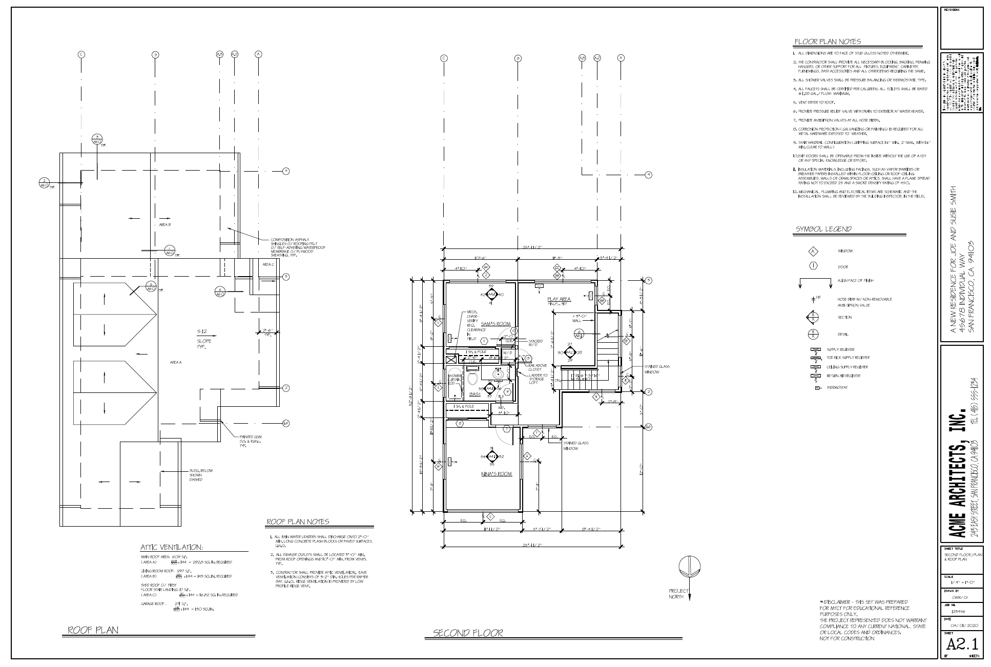
Floor plans
Imagine a view of a home sliced horizontally about five feet from the ground and looking down from above. This is the way a floor program is fatigued, and it is designed to requite you lot a detailed idea of the layout of each floor of the house. It includes features such equally walls, doors, windows, and even furniture.
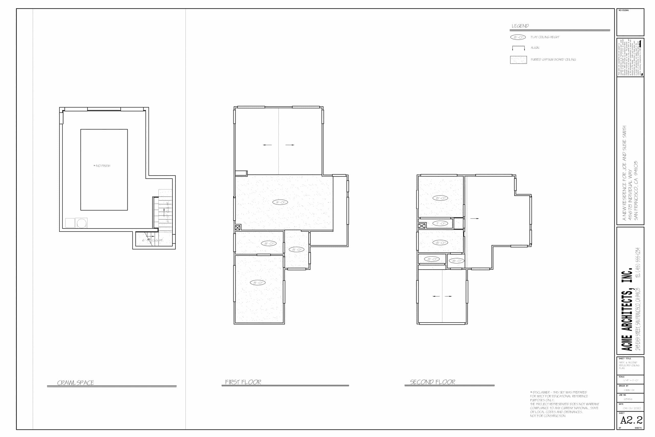
Reflected ceiling program (RCP)
The RCP is a impress that shows y'all the dimensions, materials, and other key information well-nigh the ceiling of each of the rooms represented on your blueprint. It takes its name from the idea that you are looking down at the ceiling every bit though there were a mirror on the floor reflecting the ceiling's plan back to you. (Note that this blazon of drawing isn't ever included in the blueprints package.)
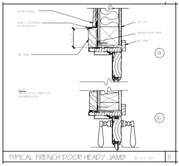
Item drawings
Special details of a firm are included in drawings whose features are magnified so that a builder can encounter how to construct these elements. Structural connections, window openings, and wall junctions tin can all be included in supplemental item drawings.
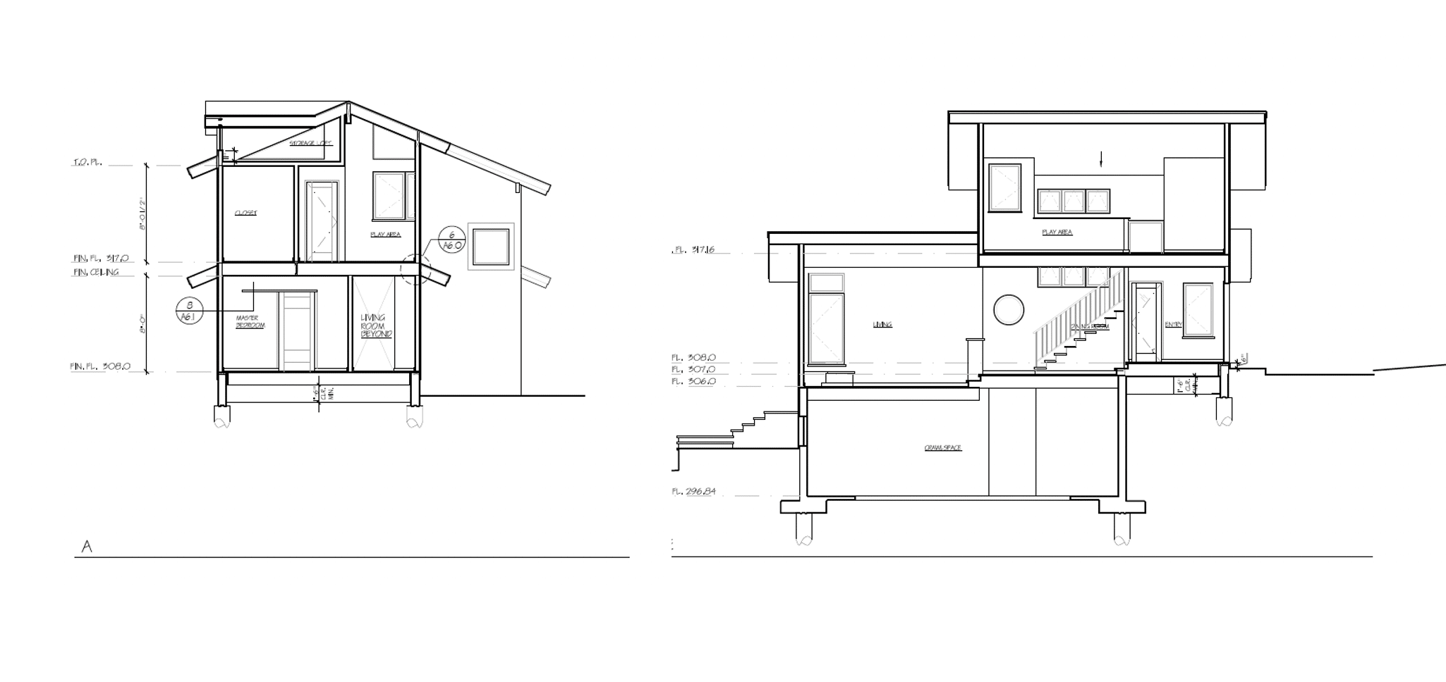
Elevations and sections
Elevations prove the vertical layout of the building, and there is usually ane elevation drawing for each face of the edifice. An exterior elevation shows yous what a house like if you're continuing front end, side by side to, or behind it. An interior peak shows the same thing, only from inside the house. Section drawings evidence what the building would expect if you were to make a vertical cut through a particular part of a building to show a cantankerous section of the construction, and how the spaces inside fit together vertically.
Structural drawings
Once the architectural drawings are consummate, the architect sends those prints to an engineer, who uses them to create the structural prints. The structural drawings testify how the house will be framed, and how the building will exist given its structure. They are shown from the ground up; in other words; you'll see a structural cartoon for each flooring of the firm. As Jordan Smith puts information technology:
"The architectural prints show how the building is supposed to look, how it'south supposed to interact with the humans that are living in it… Withal, it doesn't give you lot whatsoever information on how to build it in such a way that it doesn't fall down. The structural prints get into all of that detail."
The structural prints are sent dorsum to the architect for review, and the team signs off on them earlier they're included in the package and sent to the builder.

MEP (Mechanical, Electric, Plumbing)
Call up of MEP equally the cardinal nervous organization of a building, since every mechanical function that occurs in a building, from ensuring its air quality to planning its electronic and communications systems, to laying out circuitous piping routes, is performed past an MEP engineer. The MEP systems are normally delivered in a bundle equally divide drawings. As a builder, it'due south of import to know where those systems will be routed, so y'all tin leave space for them to be laid in.
Mechanical
The mechanical plans testify the heating, ventilation, and air conditioning (or HVAC) systems of a building. These are all elements you will observe in mechanical drawings.
- HVAC systems
- Exhaust systems
- Directly digital command (DDC) systems
- Chilled water systems
- Heating h2o systems
- Infection control HVAC
Electrical
The electrical plans show how the electric system volition provide the ability supply for lights and appliances. Electrical engineers blueprint the all-time routes for wiring and design systems that tin can be safely and continuously operated. Some of the components of electrical plans include:
- Onsite ability generation requirements and distribution
- Information technology (It) and audiovisual (AV) plans
- Lighting and fire protection systems
- Standby ability systems
Plumbing
Plumbing designs reverberate the complex piping and sewage routes for the edifice, likewise as heated h2o and rainwater collection and storage. More and more than, plumbing designers are chosen to develop efficient systems that can help subtract a building's water consumption and reduce water bills. For case, they plan low-flow fixtures in bathrooms, insulate pipe and use culling water sources. Some of the plumbing systems in MEP drawings include:
- Natural gas piping
- Domestic warm and cold water
- Acid waste piping
- Tempest drainage systems
- Vacuum/compressed air
How to read blueprints
First, understand that the unabridged package of drawings includes split aspects of the construction that together reflect all the construction elements of the firm. In guild to get a complete picture show of a firm, start reading construction plans at the beginning, starting with the site program. The plans give progressively more structural detail as you advance through the package.
Abbreviations and symbols
The number of details that must exist included in a consummate set of blueprints is and then large that architects reduce the information on the drawings to a ready of standardized symbols and abbreviations in order to brand the drawing easier to read and less cluttered.
For reference, every set of architectural drawings includes a symbol legend. If yous aren't familiar with a symbol, you will exist able to discover it in the legend. Flooring program notes give additional context for the edifice. For instance, the notes can clarify exactly to what signal on a wall dimensions should be measured.
Every symbol on the legend is drawn to the aforementioned scale equally the residual of the flooring plan. About plans include symbols that are a combination of advent (for instance, a bath looks like a bathroom); conventions (double lines are commonly used to denote walls); and labels (for instance, a thermostat is labeled "T").
Scale
In order to fit all the information well-nigh a layer of a building onto a page, construction drawings and architectural drawings are drawn and so that a small increment of measurement represents a larger increase. This means that the plans are drawn "to scale."
Scales vary in complexity, from the uncomplicated (1 inch = 1 foot) to the complex (3/xvi inch = 1 foot). The symbols are besides fatigued to scale so y'all volition become an authentic idea of how elements of a room are configured in the space.
The scale is always shown on the aforementioned page as the drawing, either nether the title or below an private drawing. Keep in mind that scales can vary throughout a set of architectural prints, and so check each page and use an architectural scale , or scaled ruler, to make certain you're reading the print accurately. If you don't own one already, it's an essential tool of the merchandise for architects, engineers, and builders that yous will desire to buy now. You tin also download a simple printable version from Archtoolbox .
iii perspectives: plan, elevation, and sections
A floorplan is the building plan that is almost familiar to about people: a bird's-eye view of a building with all the elements laid out on a horizontal plane. But in order to sympathize the construction in three dimensions, you lot'll need to be able to read the program, elevation, and sections together. For instance, while an elevation drawing will show what a house looks like if you're continuing side by side to its exterior or interior walls, the section view provides vital insight into how the construction volition stand up.
While elevations and sections are both vertical representations of a design concept, the department view reveals details of the construction of walls and the thickness and height of beams and other support. Working all together, these three types of drawings volition give you the full picture of the structure of the business firm.
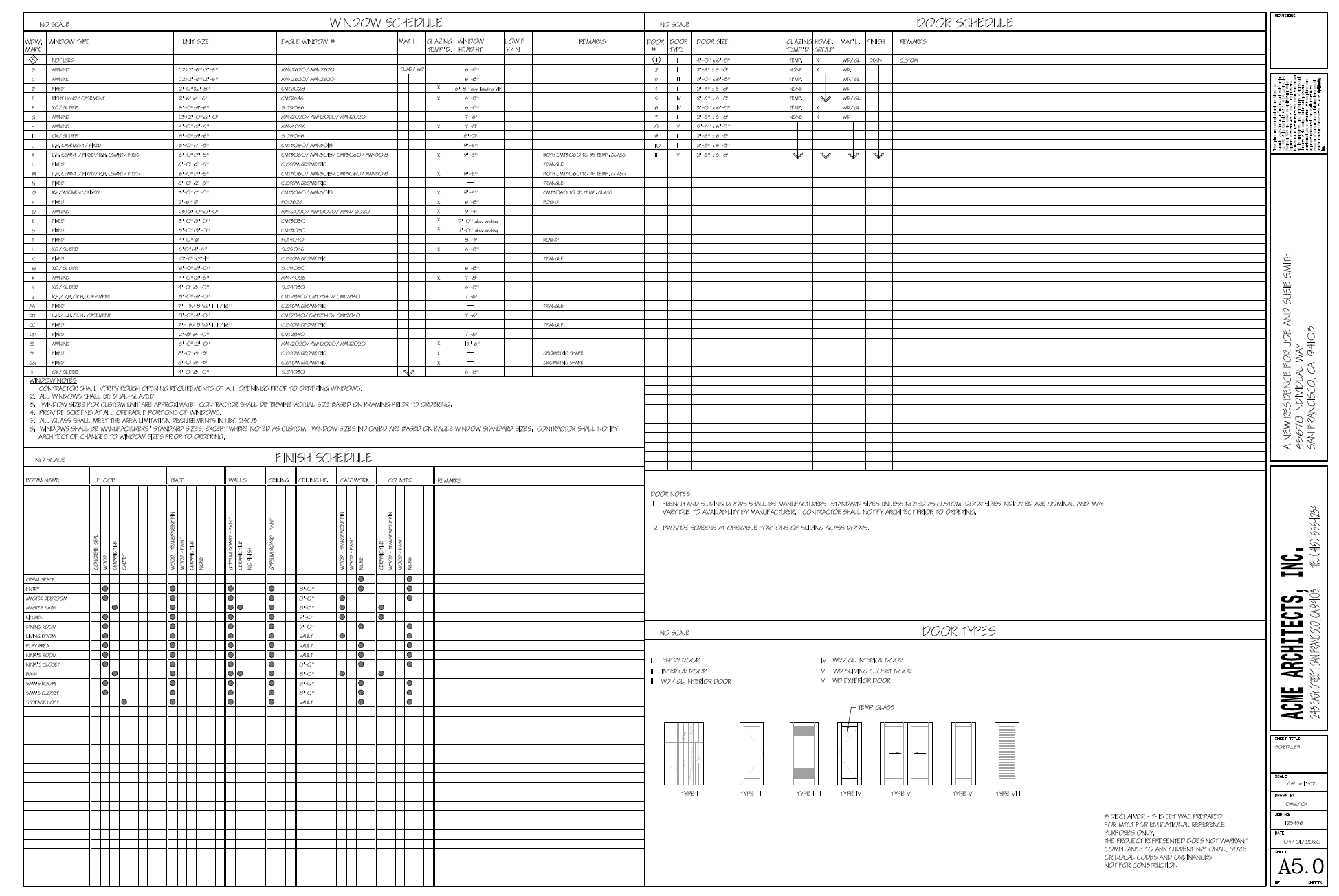
Schedules
These documents testify a listing of materials and products necessary for the structure, and the society of installation. Typical schedules include doors and windows and room finish schedules.
What is the relationship between blueprints and construction planning?
It'southward important to understand who's involved with the blueprints as the construction planning happens. In general, an architect will send the architectural drawings to an engineer, who plans the structural prints to work with the architectural plans. The structural prints are sent back to the architect to review. All parties should sign off earlier they are sent to the builder to execute.
MT Copeland offers video-based online classes that requite you a foundation in construction fundamentals with real-world applications. Classes include professionally produced videos taught by practicing craftspeople, and supplementary downloads like quizzes, blueprints, and other materials to help you lot master the skills.
Source: https://mtcopeland.com/blog/how-to-read-blueprints-complete-guide/
0 Response to "How to Read Plan and Profile Drawings Storm Drains"
Post a Comment